Reliability
Reliability 3 Know-How
Quality
- We design an optimum structure considering base isolation and seismic resistance, which are the most important factors for DC.
- We pursue low PUE(※1) and adopt the most appropriate facility system in consideration of the surrounding environment.
*1 PUE (Power Usage Effectiveness): An indicator of the energy efficiency of IT-related facilities such as data centers, which is obtained by dividing the total power consumption of a facility by the power consumption of IT equipment.
Safety
- We conduct safety education and training in cooperation with partner companies.
- We ensure a safe and environmentally comfortable working environment.
- We take thorough measures to prevent fire and infection at work sites.
Environment
- We provide the best solutions to carbon neutrality.
Various technologies and achievements that contribute to "Quality", "Safety" and "Environment"
Structure
Achievement of data centers resistant to earthquakes
- The seismic resistance of the building is set through interaction with the client.
- We develop seismic input for the building based on the ground characteristics of the construction site and the surrounding environment.
- We use our high-performance seismic isolation technology to achieve a building structure that meets the client's requirements.
- We calculate the economic loss of the designed building due to earthquakes by using the seismic risk evaluation method developed by Obayashi.
Input earthquake ground motion considering the geotechnical characteristics of the construction site
- The seismic ground motions for the design are created taking into consideration the amplification of seismic waves due to the ground of the proposed site.
- The seismic input for the design will be developed considering the long-period seismic motion, and its effect on the building will be evaluated.
【Method of creating input seismic wave for design】
Historical Waves |
The historical seismic waves are used considering the characteristics of the building. |
・El Centro wave・Taft waves・Hachinohe waves |
|---|---|---|
Published Wave |
Create simulated seismic waves that conform to the acceleration response spectrum at the release engineering base specified in the Notification No. 1461, No. 4 (e) of the Ministry of Construction in 2000. |
・Published wave 3 |
Site Wave |
A model fault model is used for the seismic epicenter to create a simulated seismic wave, which reflects the ground characteristics of the planned site. The seismic wave is created by using GIS (Geographic Information System) and considering the database of historical earthquakes, active faults, and observed earthquakes in the surrounding area. |
・Kanto Earthquake |
-
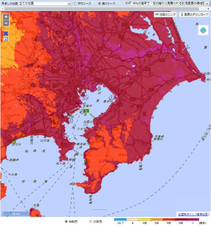
Seismic hazard map of the Kanto region(Map of areas of measured seismic intensity that have a 10% probability of being struck by a certain tremor in 50 years)
Reference: National Research Institute for Earth Science and Disaster Prevention "J-SHIS Map
Seismic Risk Assessment Technology
- The seismic risk assessment method developed by Obayashi can predict the economic loss of buildings due to earthquakes.
- The seismic risk of the construction site is evaluated using the latest seismic data for PML (the amount of loss with a 10% probability of exceedance in 50 years).
- The results of the seismic risk assessment can be used to propose cost-effective earthquake countermeasures and support the formulation of business continuity plans (BCP).
-
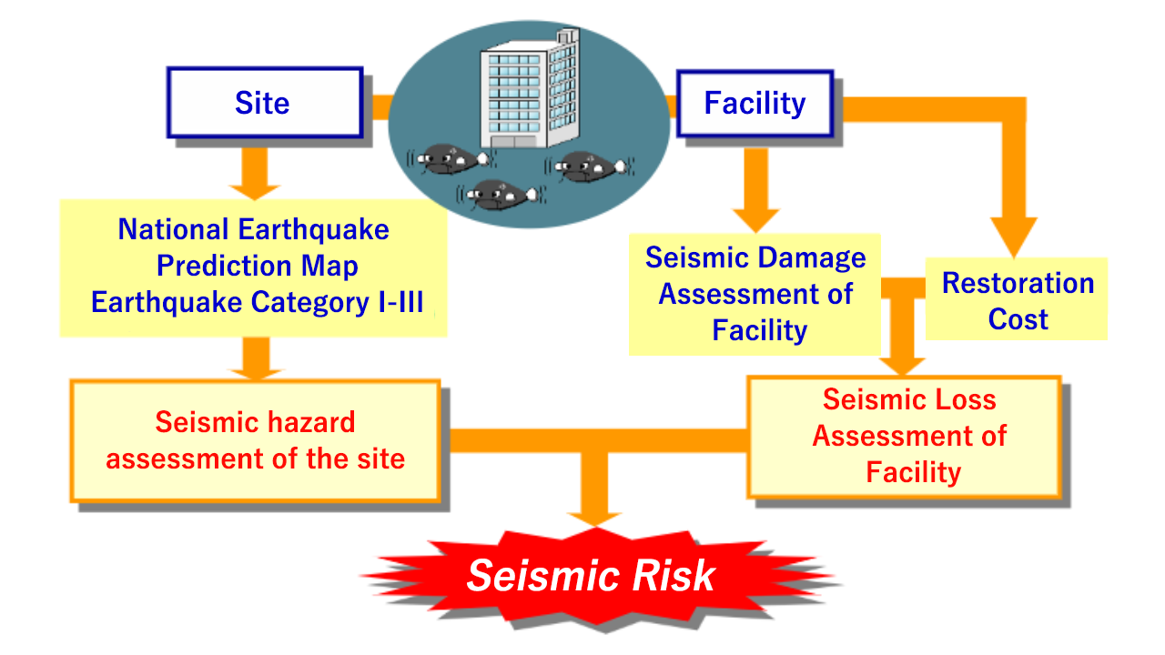
Seismic risk assessment flow
-
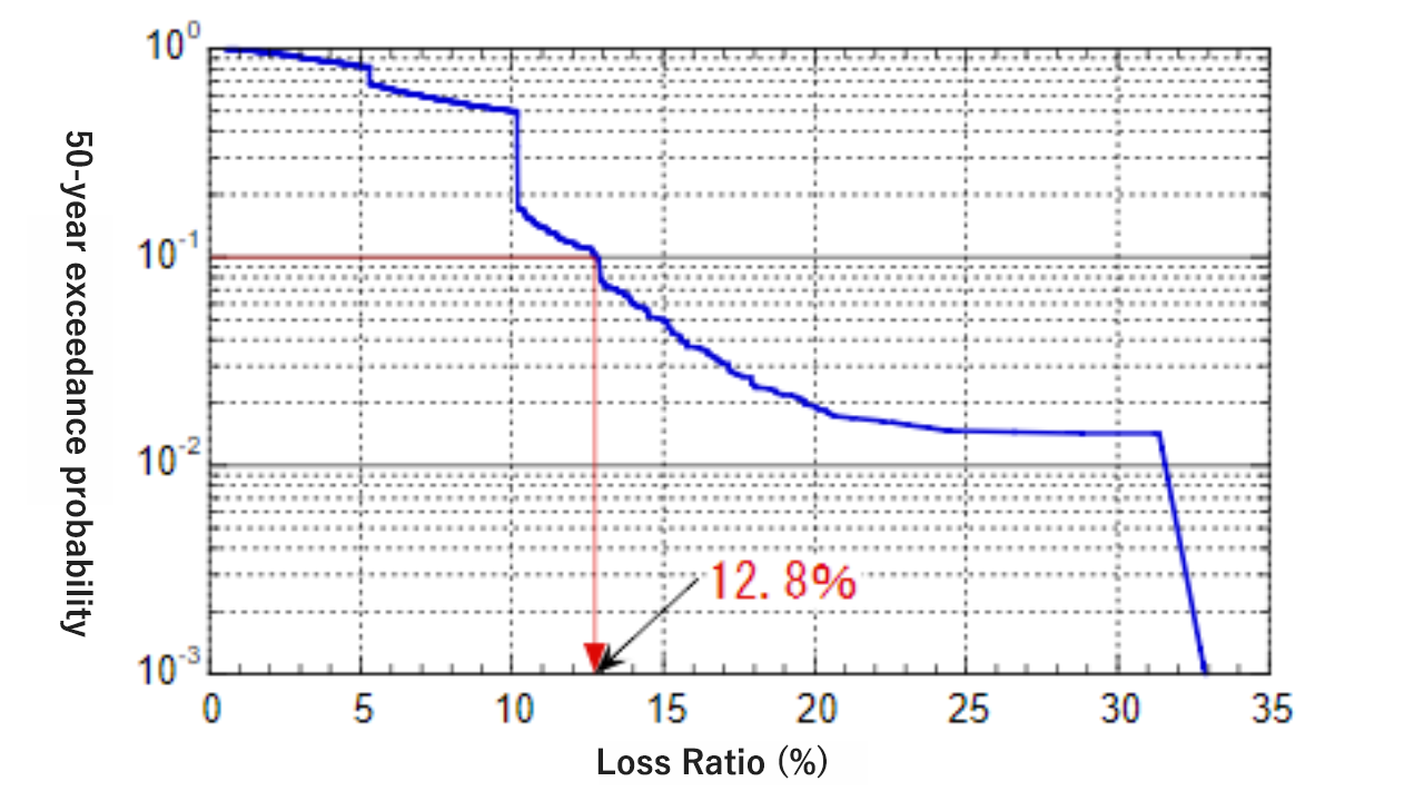
Example of seismic risk assessment
We propose the most appropriate building structure system
- We propose the most appropriate structural system according to the building's requirements and budget.
- There are three major types of structural systems that ensure building safety against major earthquakes.
-
Seismic Structure
Resists seismic forces with the strength and rigidity of its structural frame. Construction costs are relatively low.
The risk of damage to the building and its furnishings is highest because the seismic shaking is greater than in other types of buildings. -
Damping structure
Damper devices control seismic response and reduce damage to the structural frame. It can also reduce building vibration during earthquakes, thereby improving the safety of building occupants and the ability of equipment in the building to topple or move.
-
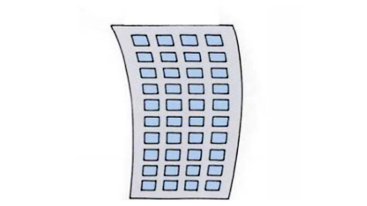
Seismic isolation structure
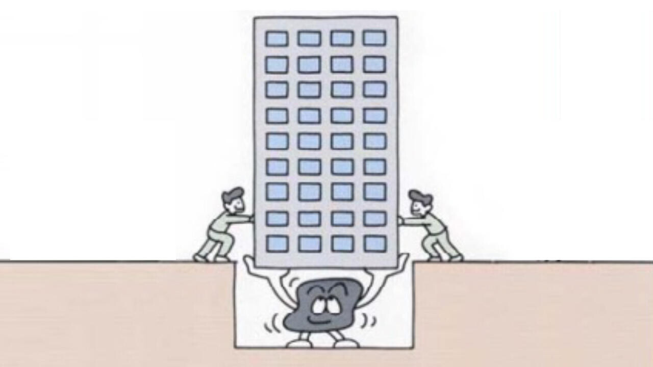
Seismic isolators absorb seismic vibration and prevent it from being transmitted to the building.
Since this system reduces the risk of servers and equipment falling over or moving, it is increasingly being used in data centers these days.
Obayashi, a leader in seismic isolation structures, protects data centers from earthquakes.
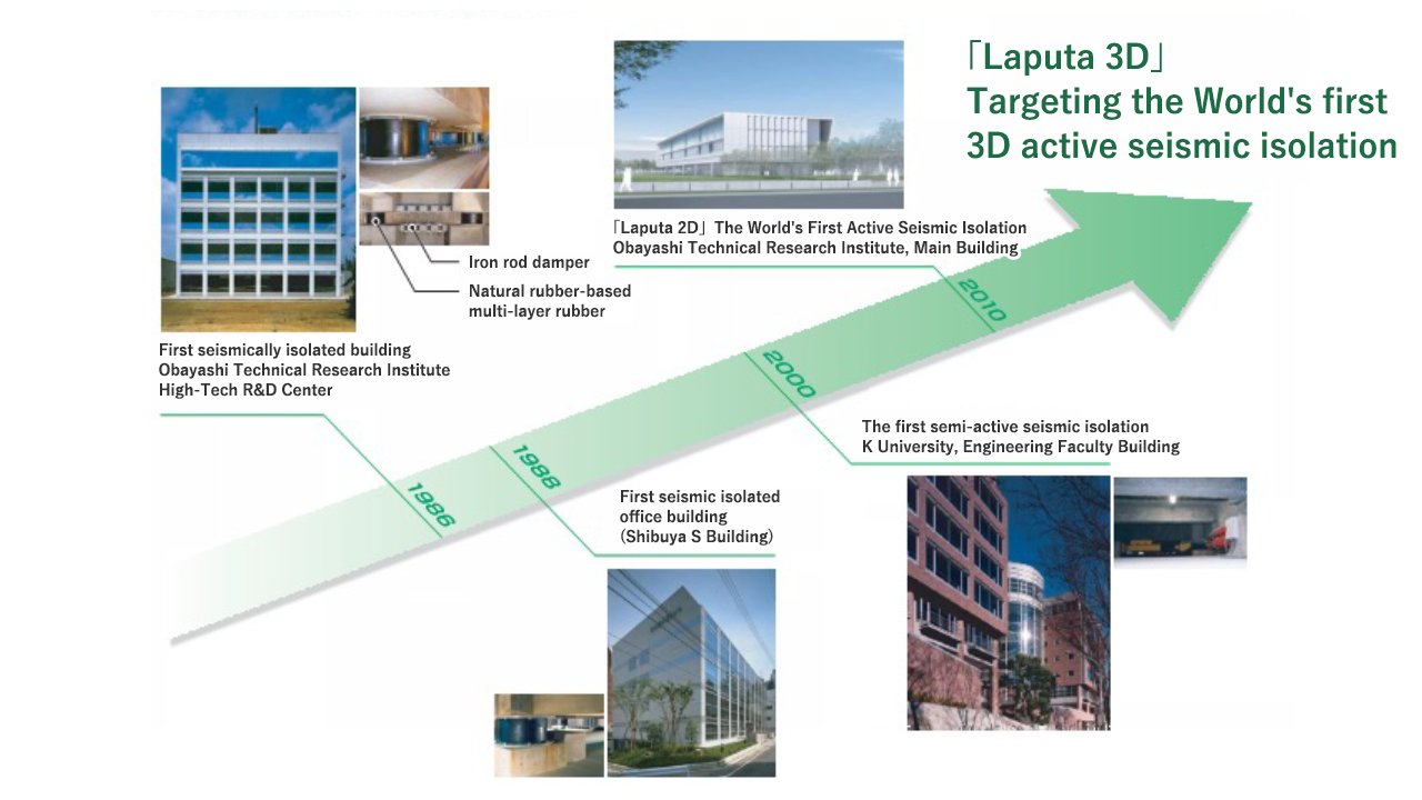
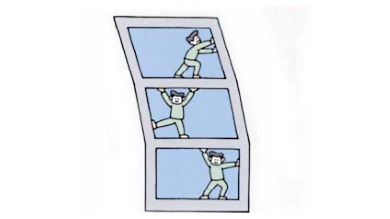
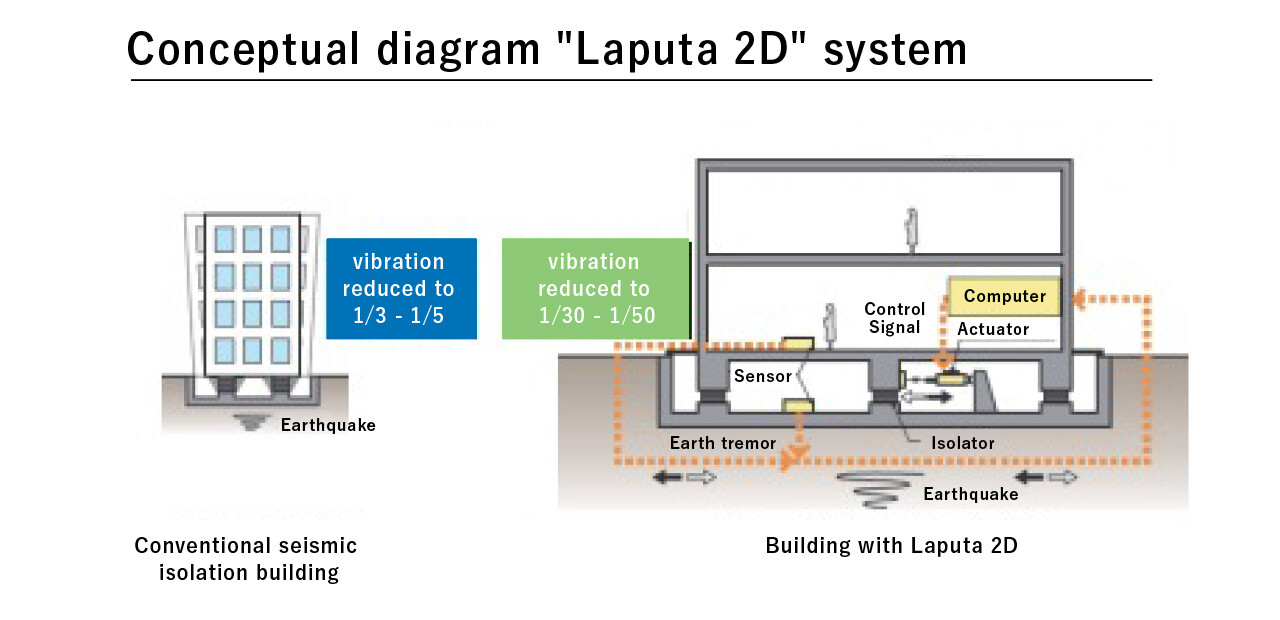
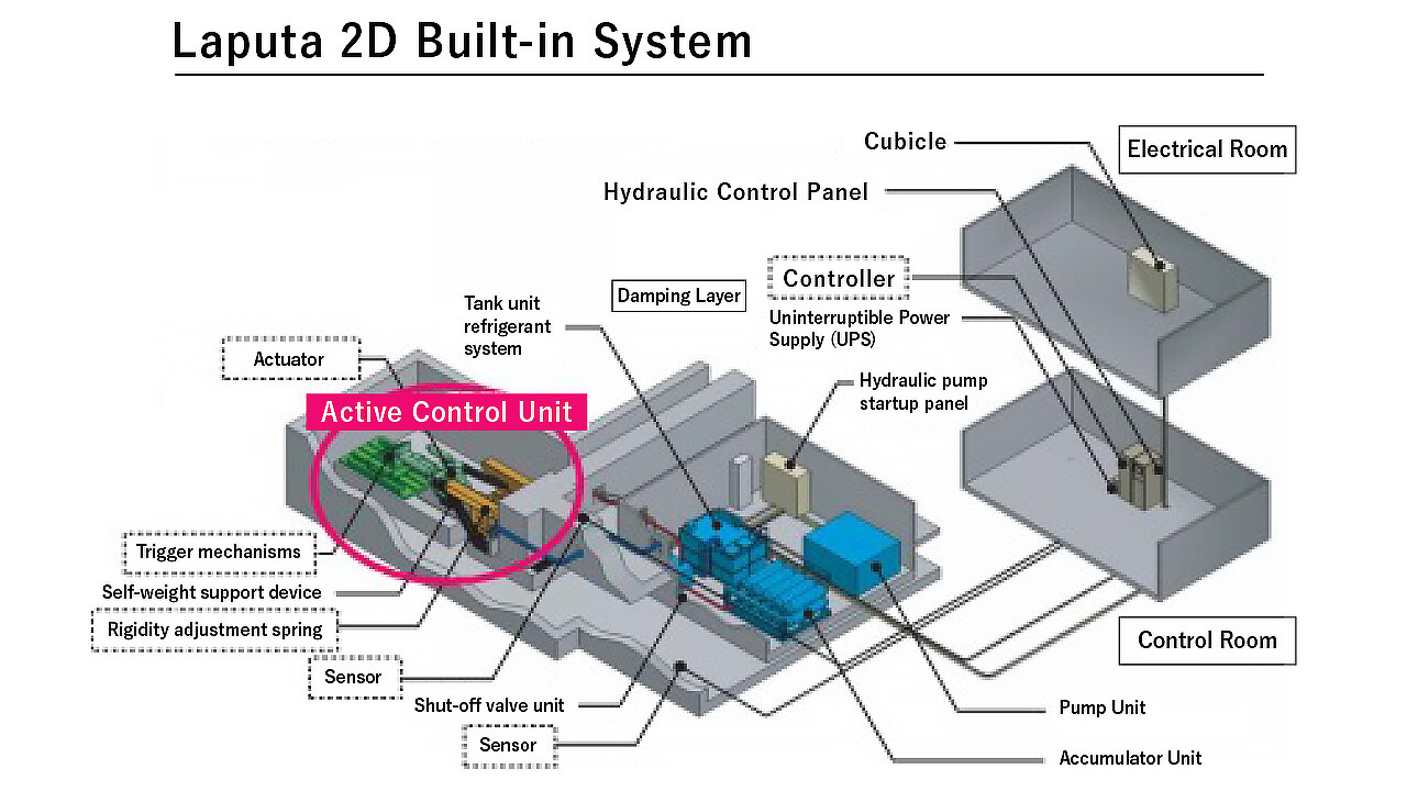
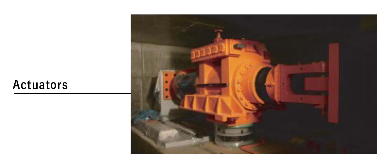
The world's first super active vibration control system "Laputa 2D"
- Conventional seismic isolation systems are capable of reducing building vibration to 1/3 to 1/5 of seismic vibration.
- Super Active Seismic Response Control "Laputa 2D can reduce building vibration to 1/30 to 1/50 .
Seismic isolation fenders
- The cushioning device is installed between the seismically isolated building and the retaining wall. The high-damping rubber cushioning material absorbs the energy of the collision through plastic deformation and mitigates the impact force.
- This improves the safety of the building and its occupants in the event of a larger-than-assumed earthquake.
-
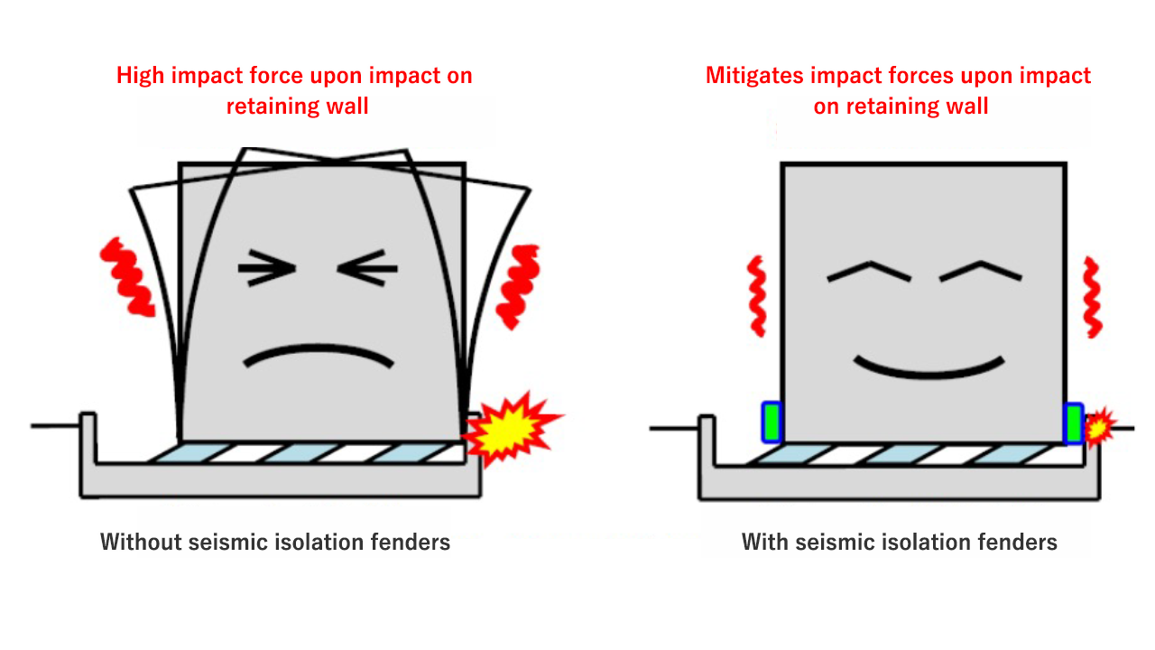
Collision condition of the building with and without seismic isolation fenders during a larger than assumed earthquake.
Reference Link
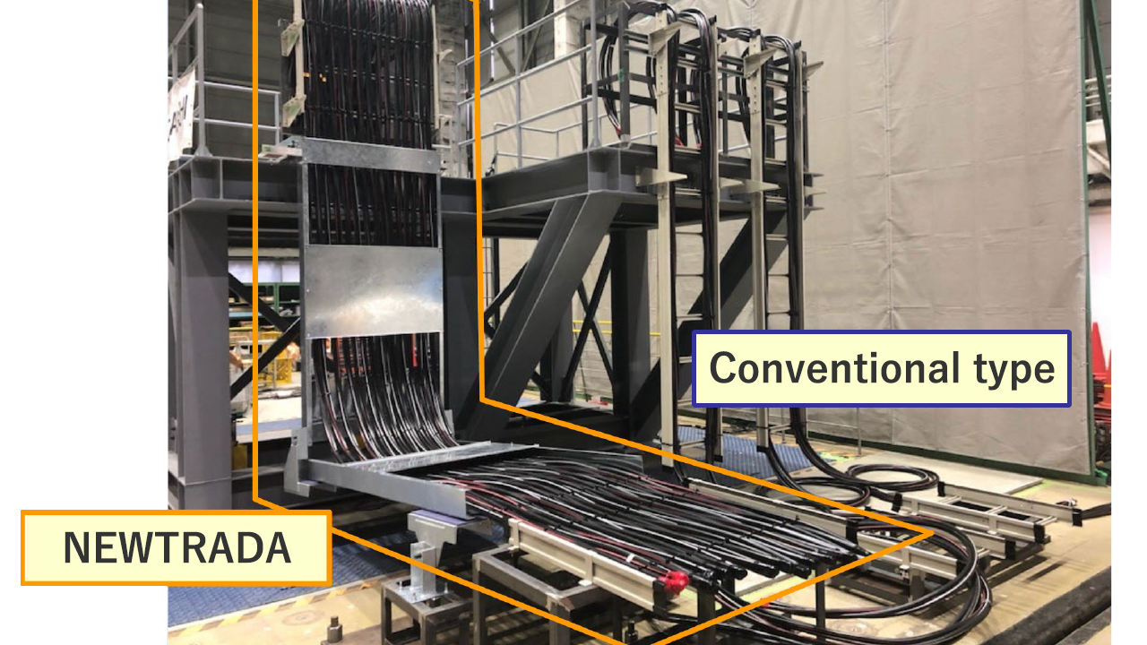
NEWTRADA【Obayashi's proprietary technology】
The NEWTRADA is a cable rack for seismically isolated buildings that moves in response to seismic vibration by pin-jointing the racks together. By placing cables on the rack, the cables also move while being supported by the rack during an earthquake, reducing the risk of damage or cutting and facilitating maintenance. In addition, the swing width of the cables is also reduced, eliminating the need to provide extra length and optimizing cable length for space saving cabling.
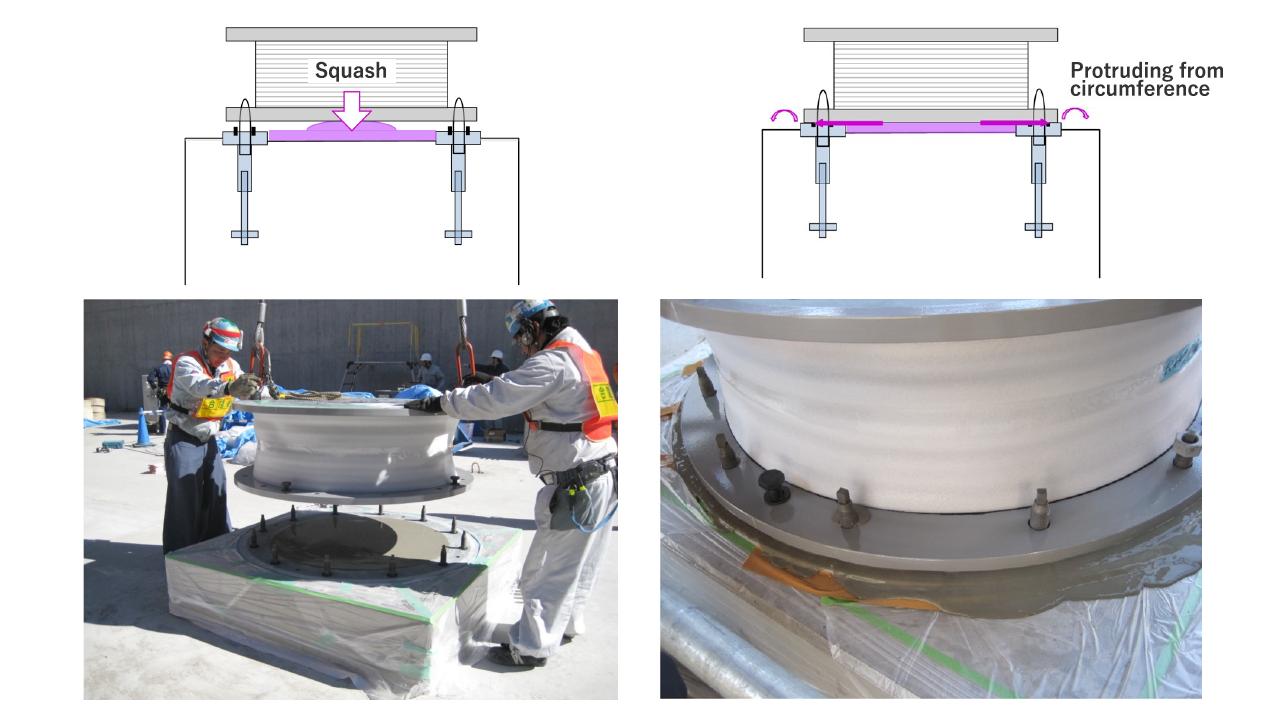
Pressurized Filling Method for Seismic Isolation Devices【Obayashi's proprietary technology】
~Labor-saving cost reduction and quality improvement~
- Labor-saving, low-cost, and quality-stabilizing seismic isolation installation method
- The "seismic isolation device pressure-filling method" is a new method in which a gauge plate is installed on a normal concrete foundation and the gap between the gauge plate and the flange plate on the seismic isolation device side is crushed and filled with cementitious adhesive material.
- This method does not require the advanced skills and knowledge of conventional methods that use high-fluidity concrete to fill the entire area under the base plate, and it is easy to control quality and reduce costs because grouting is not required.
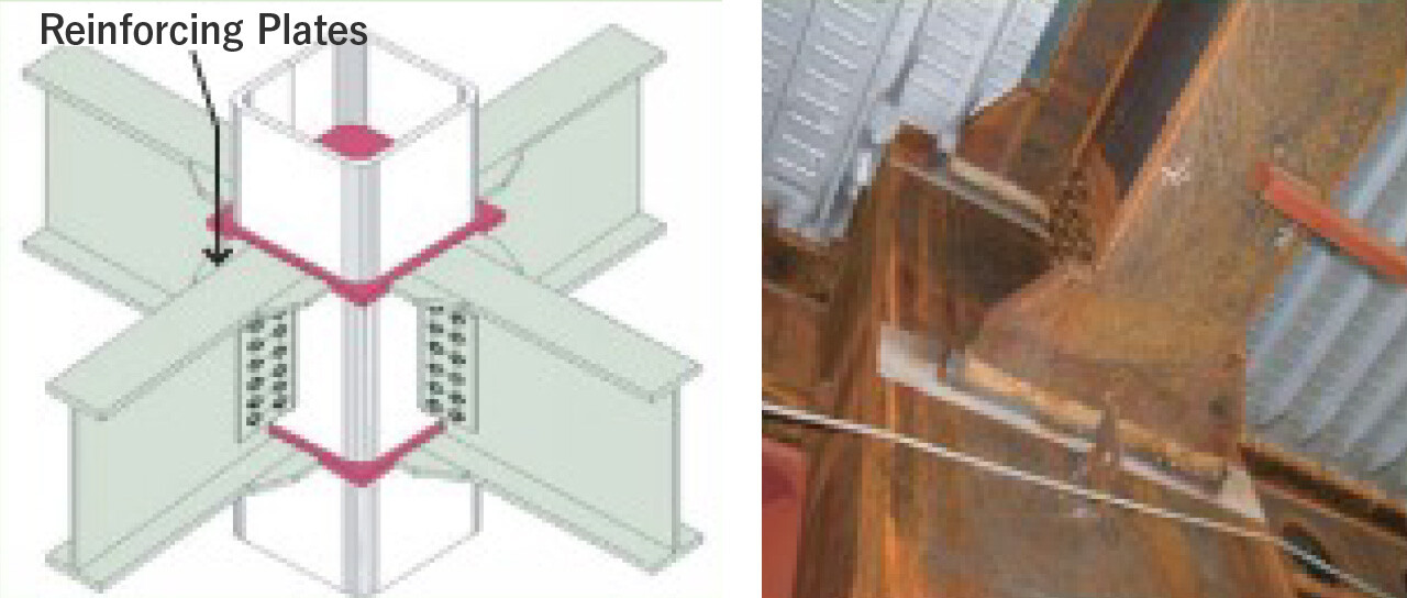
Wing Beam Method
The end of the main beam is reinforced in a haunched shape, and the position of maximum stress generation is shifted away from the end joint cross section where the weld and high-strength bolt joints overlap.
- High strength and tenacity are achieved.
- Highly reliable column-beam joints are achieved.
- Economical design
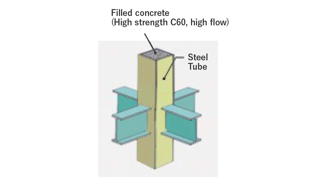
CFT Columns (Concrete Filled Steel Tube)
By filling high-strength, high-fluidity concrete into square steel tube columns, superior structural performance is achieved compared to steel tube columns alone.
Facility(MEP)
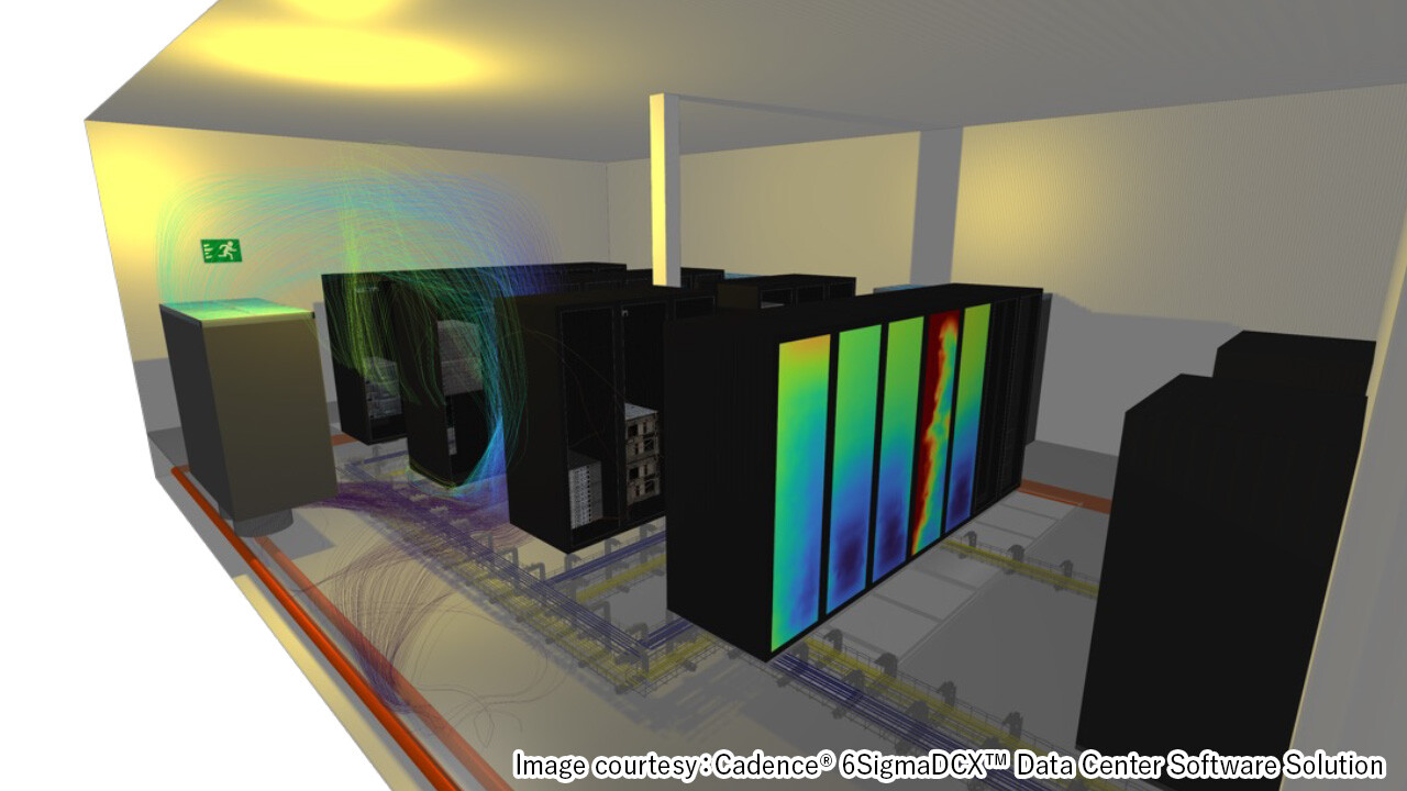
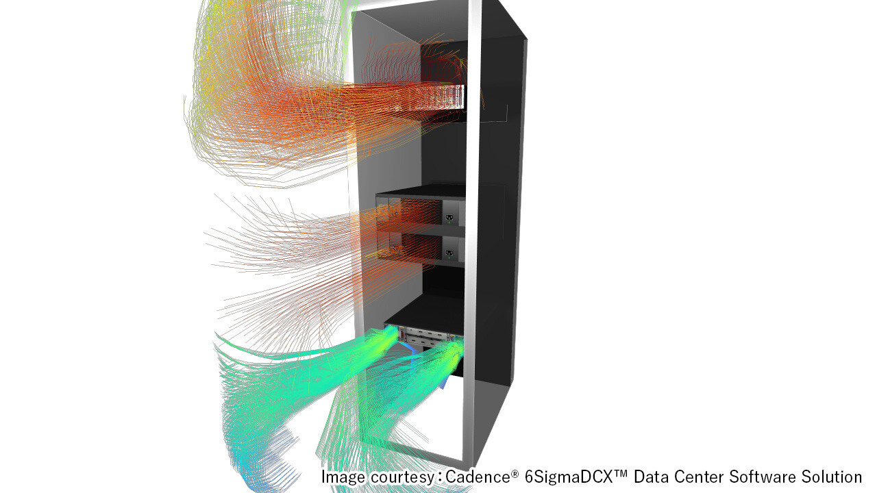
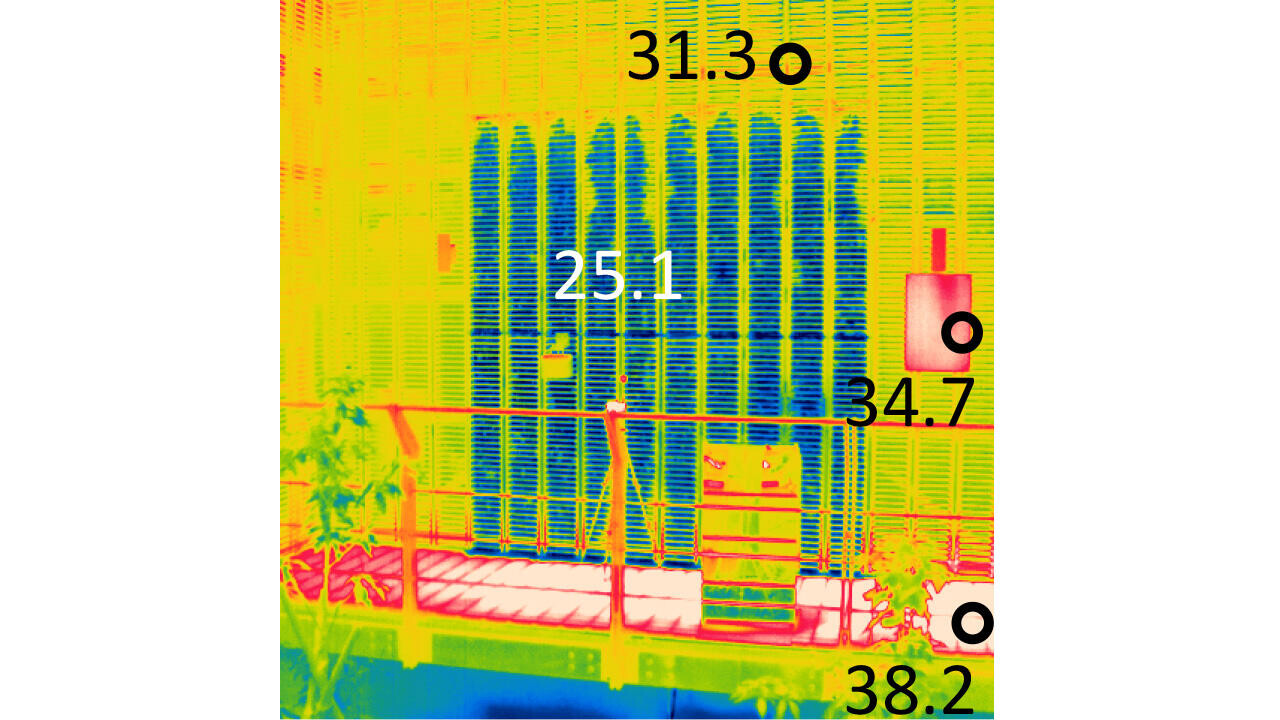
Preliminary study with visualization of temperature and airflow
By visualizing the temperature and airflow environment of various locations inside and outside the data center with digital twin technology and conducting preliminary studies, efficient air conditioning plans can be developed to save energy and prevent malfunctions as well.
Temperature Distribution around Racks
- Preliminary study of airflow in data halls and temperature distribution of air around rack suction surfaces and racks.
-
Sudy of airflow in data hall and temperature distribution on rack suction surface (example)
-
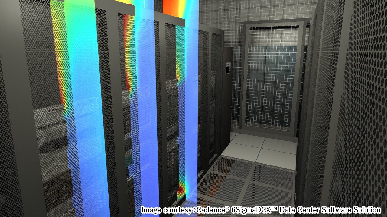
Study of Z-axis distribution of air temperature around rack (example)
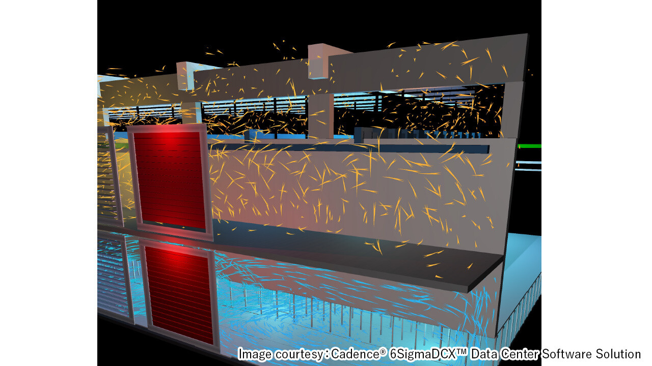
Impact of Outdoor Wind Velocity Distribution and Exhaust Heat
- By taking outdoor wind velocity into account in the temperature distribution outside the building, the impact of exhaust heat from the data center on the neighboring environment is considered in advance.
-
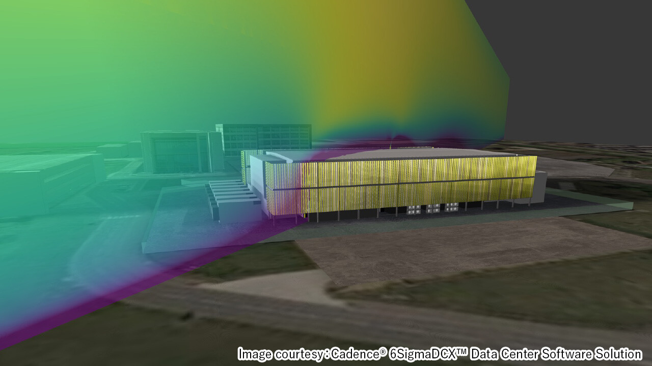
Study of outdoor wind velocity distribution (example)
-
Study of the effect of exhaust heat from cooling towers (example)
Model creation for server installation
- Preliminary study of different air temperature distributions depending on server installation patterns.
-
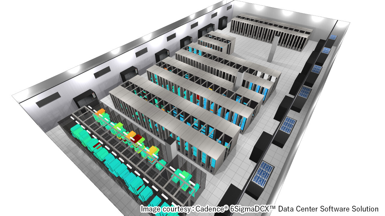
Develop a model of the server installation state (example)
-
Study of airflow models for server installation conditions (example)
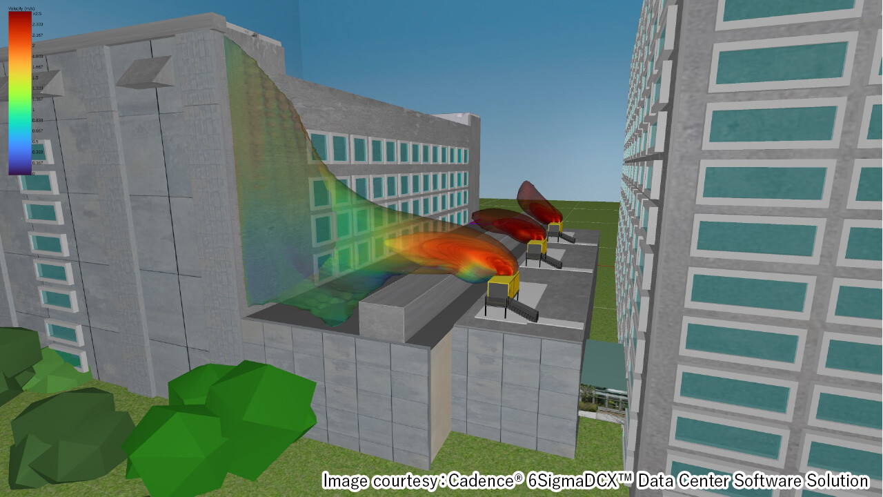
Air flow and temperature distribution in air conditioning units
- Preliminary study of air distribution around air conditioning units and air conditioning equipment rooms as well as servers.
-
Study of air velocity, air direction, and temperature distribution in an air conditioning equipment room (example)
-
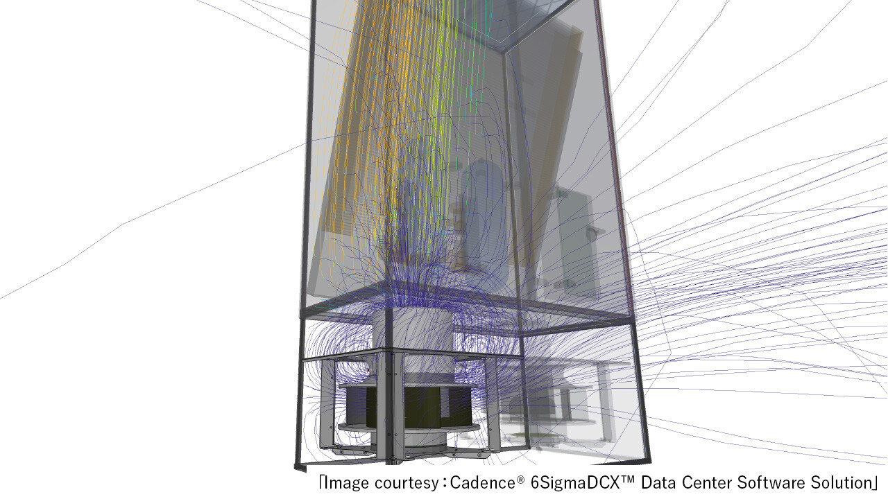
Study of detailed airflow around an air conditioner fan (example)
Environmental Technology
Optimal Environmental Technology Proposals
Obayashi proposes optimal solutions to meet diverse needs for carbon neutrality.
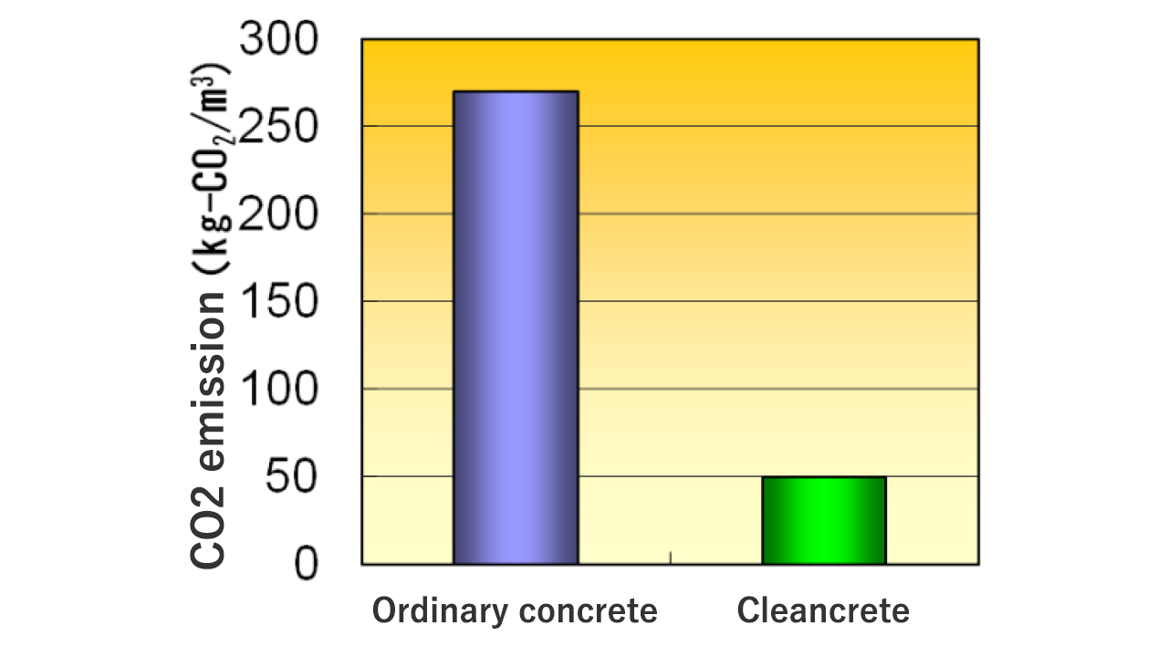
Low-carbon concrete "CLEAN CRETE"
- Part of the cement is replaced with industrial by-products such as blast furnace slag fine powder (*1) and fly ash (*2), which emit less carbon dioxide.
- Part of the cement is replaced with industrial by-products such as blast furnace slag fine powder (*1) and fly ash (*2), which emit less carbon dioxide.
※1 By-products from steel production
※2 By-products from coal-fired power generation
※3 Varies depending on materials and formulations.
Reference Link
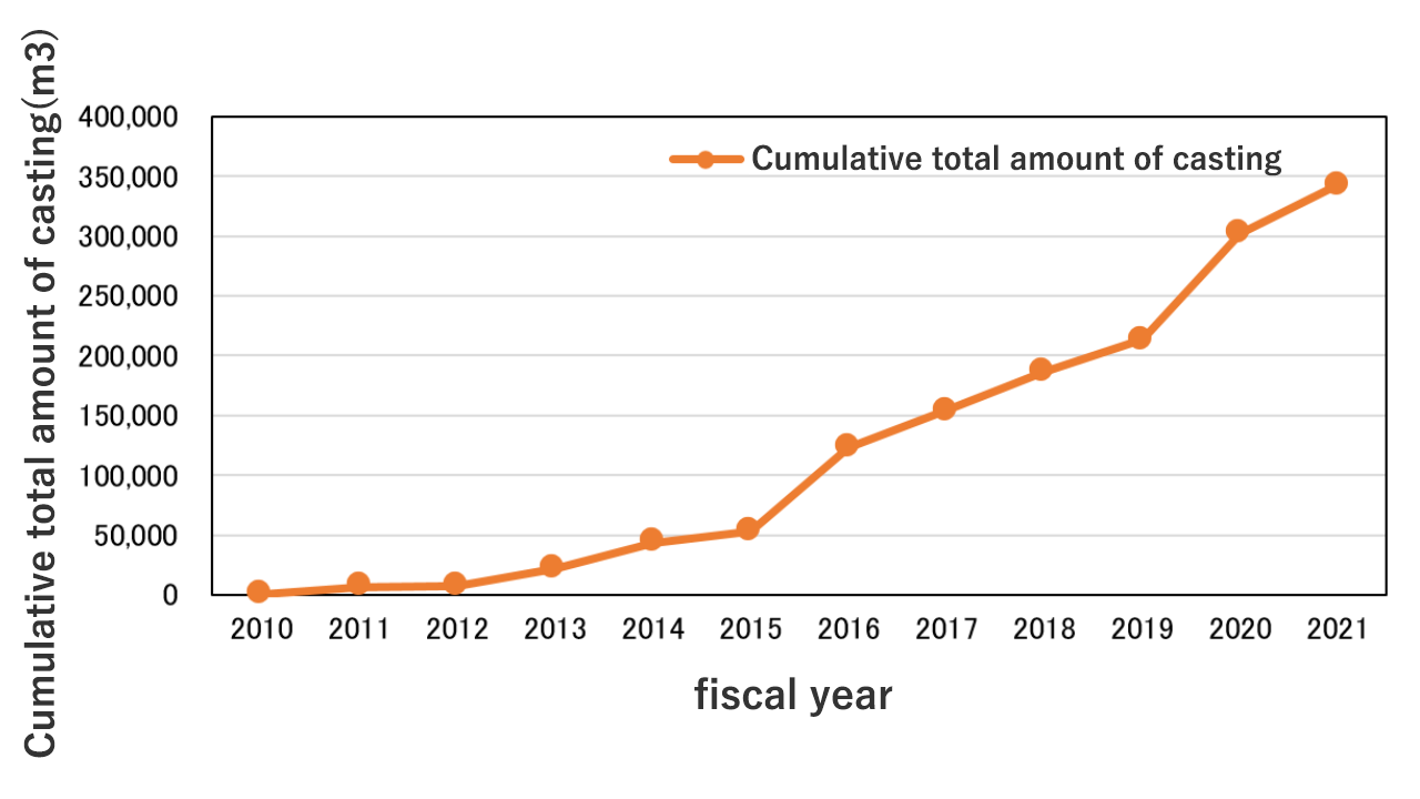
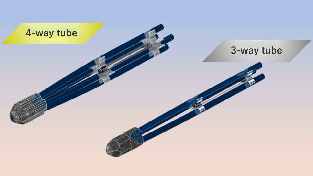
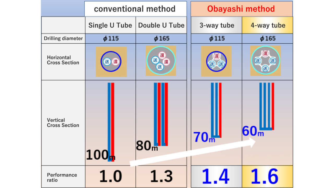
Geothermal Heat Utilization System with 4-way and 3-way Tubes
- Geothermal heat is a renewable energy source that can be used stably, and an efficient heat pump system can be built using the seasonal temperature difference from the ground.
- Obayashi's system has developed and commercialized a geothermal heat exchanger that is more efficient and less expensive than conventional systems.
Reference Link
Water retaining cooling panel "Uchimizu-Wall"
- In recent years, various thermal environmental countermeasures have been required to deal with extreme summer heat, and those that utilize the vaporization heat of water, such as mist spraying and water sprinkling, are effective.
- "Uchimizu-Wall" is an exterior wall material that cools a space with the vaporization heat of water. It cools both the space and people by dripping a small amount of water onto the exterior wall to moisten it.
-
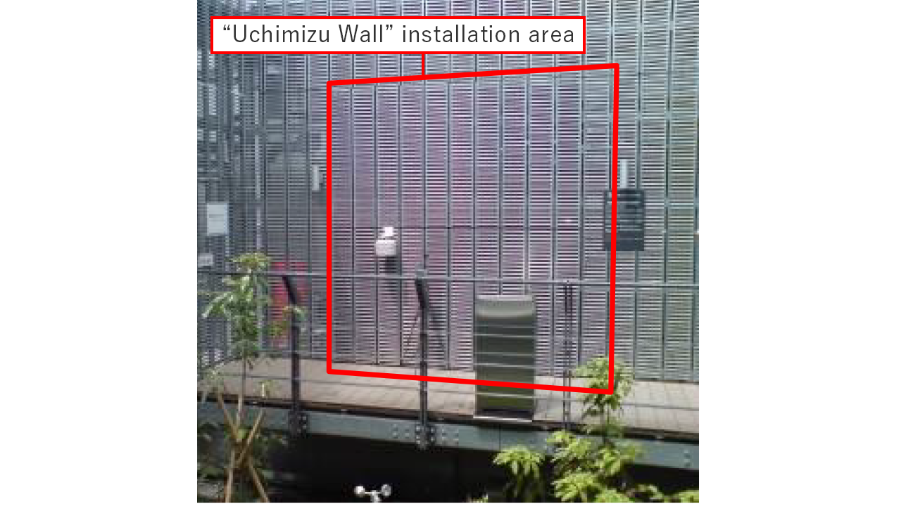
*Caption for Figure Automatic water supply by drop type system
-
Decreases surface temperature by approx. 10°C, improves indoor thermal environment
Reference Link
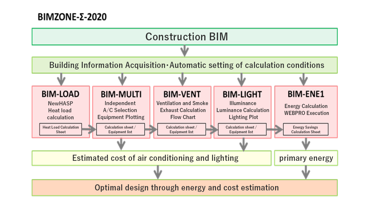
「BIMZONE-∑-2020」, Facilities Design Support System
- This tool is designed to optimize energy and costs through facility design support linked to BIM.
Reference Link
Green Energy
Obayashi's Green Energy Business
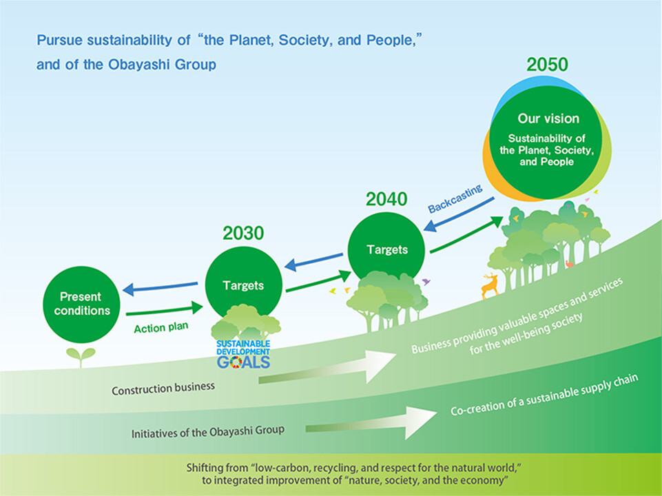
Obayashi is developing each of its businesses under the "Obayashi Sustainability Vision 2050", a medium- to long-term environmental vision that aims to pursue sustainability through harmonious coexistence of the 「The Planet , Society, and People」 and the sustainability of the Obayashi Group at the same time.
Obayashi Group's new challenge is to develop environmentally friendly and sustainable 「 Green Energy 」.
-
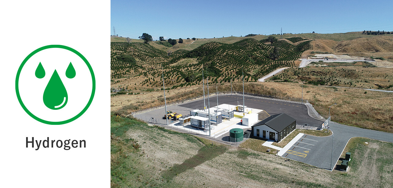
From 2021, we are expanding our green hydrogen business, which aims to build a hydrogen production and supply network using geothermal energy at two sites in Taupo, located in the central North Island of New Zealand, and Kokonoe Town, Oita.
-
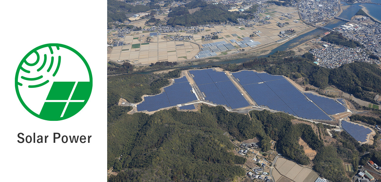
In July 2021, when the Feed-in Tariff (FIT) system of the Re-energy Special Measures Law came into effect, we became the first general contractor to operate a commercial solar power plant in Kumiyama-cho, Kyoto. Currently, 40 facilities are in operation at 28 locations in Japan.
-
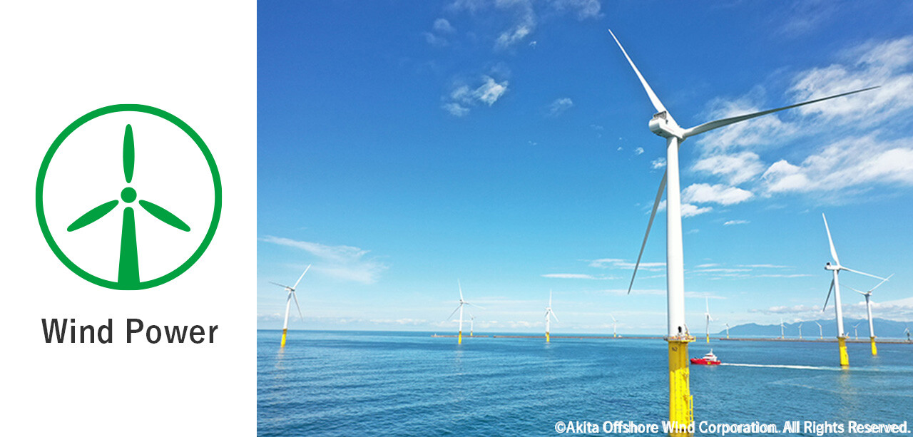
We started operation of an onshore wind farm in Mikusa-machi, Akita in November 2017 and in Rokkashomura, Aomori in April 2022. We are also involved in the Akita and Noshiro Port Offshore Wind Farm Project, Japan's first commercial large-scale offshore wind power generation project, which fully opened in January 2023. We are also focusing on the development of construction technology and machinery to support the commercialization of the business.
-
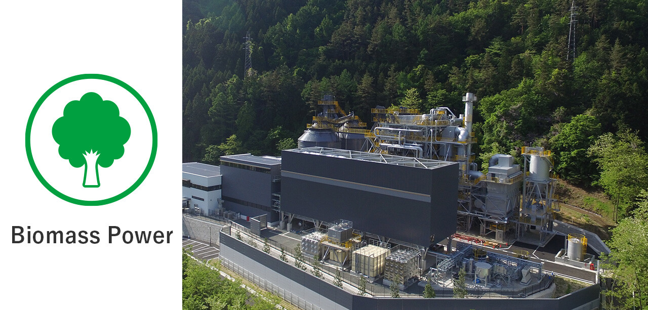
In December 2018, we became the first general contractor to operate a woody biomass power plant fueled by domestic timber in Otsuki City, Yamanashi. in February 2022, a biomass power plant is also operating in Kamisu City, Ibaraki.
-
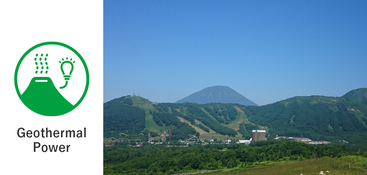
Full-scale drilling surveys are currently underway in Kyogoku Town and Rusutsu , Hokkaido, Japan, with funding from the Japan Oil, Gas and Metals National Corporation (JOGMEC).
-
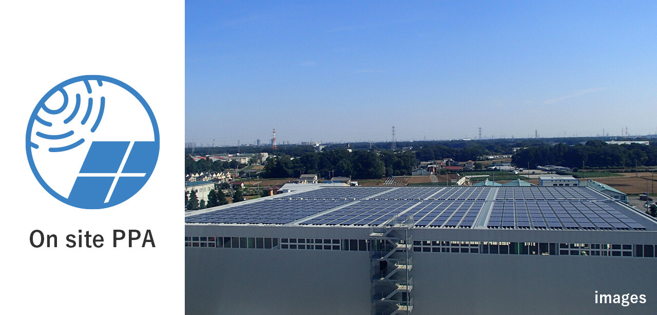
Since March 2023, we began supplying electricity through on-site PPA (third-party ownership model). On-site PPA is a service that provides free installation, maintenance, and operation of photovoltaic power generation systems on the sites of electricity consumers or on factory roofs and is attracting attention as a new business model for the solar power generation business.
-
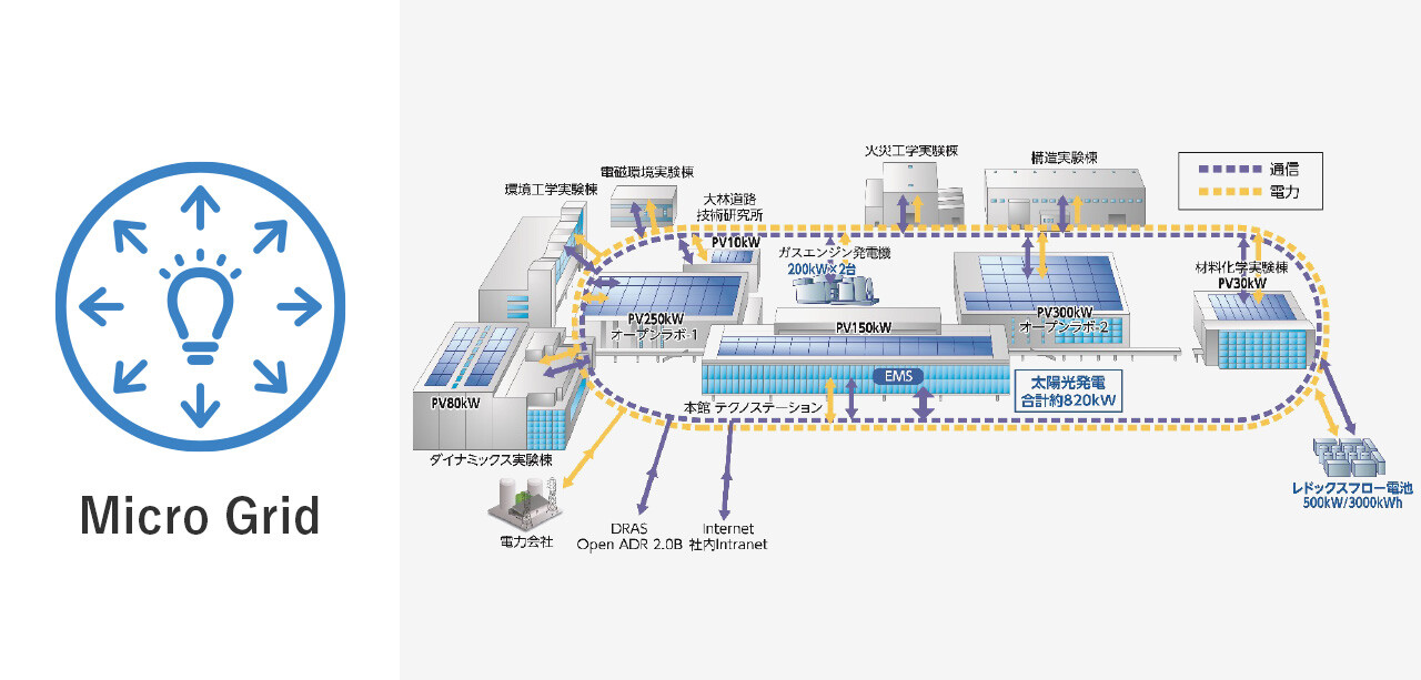
Since 2011, a microgrid combining commercial electric power with photovoltaic power generation systems, lithium-ion batteries, and cogeneration systems that supply heat and power has been constructed at the Technical Research Institute in Kiyose, Tokyo, and research is underway to explore the effectiveness of a model of local production for local consumption of energy.
Experience
Major Obayashi Group Construction Projects
- We have experience in many data center construction projects.
- We provide the best solutions for our customers based on our experience. We have experience not only with domestic and Japanese companies, but also with foreign and foreign-affiliated companies.
- We are able to respond to a wide variety of customers both domestically and internationally.
| Type of Owner's Business | Location | Completion | Floor Area m² | MW |
|---|---|---|---|---|
| Service(Japan) | Osaka | 2022 | 3,000 | 3.0 |
| Think Tank(Aus) | Osaka | 2022 | 12,000 | 12.0 |
| Information (UK) | Chiba | 2022 | 26,000 | 18.0 |
| Information (UK) | Chiba | 2021 | 23,000 | 27.0 |
| Information (UK) | Chiba | 2020 | 36,000 | 27.0 |
| Information (Japan) | Tokyo | 2020 | 65,000 | 48.0 |
| Financial (Japan) | Kyoto | 2018 | 47,000 | 36.0 |
| Information (UK) | Chiba | 2018 | 16,000 | 15.0 |
| Service(Japan) | Osaka | 2016 | 15,000 | 3.6 |
| Information (Japan) | Osaka | 2015 | 46,000 | 30.0 |
| Real Estate (Japan) | Chiba | 2014 | 40,000 | 45.0 |
| Information (US) | Chiba | 2014 | 5,000 | 6.0 |
| Real Estate (Japan) | Osaka | 2012 | 18,000 | 12.0 |
| Information (Japan) | Osaka | 2011 | 11,000 | 9.0 |
| Service(Japan) | Tokyo | 2011 | 13,000 | 9.0 |
| Financial (Japan) | Osaka | 2010 | 22,000 | 15.0 |
| Information (Japan) | Tokyo | 2010 | 5,000 | 3.0 |
| Research (Japan) | Hyogo | 2010 | 13,000 | 9.0 |
| Service(Japan) | Kanagawa | 2009 | ― | ― |
| Information (Japan) | Hyogo | 2008 | 22,000 | 15.0 |
| Financial (Japan) | Tokyo | 2008 | 13,000 | 9.0 |
| Service(Japan) | Tokyo | 2006 | ― | ― |
| Information (Japan) | Tokyo | 2006 | 3,000 | 3.0 |
| Financial (Japan) | Kyoto | 2003 | 3,000 | 3.0 |
| Service(Manufacture) | Gifu | 2003 | ― | ― |
| Information (Japan) | Tokyo | 2002 | ― | ― |
| Information (Japan) | Osaka | 1999 | ― | 6.0 |
| Financial (Japan) | Osaka | 1998 | 8,000 | 6.0 |
| Construction (Japan) | Chiba | 1996 | ― | ― |
| Financial (Japan) | Chiba | 1996 | ― | ― |
Major Obayashi Group Construction Projects(Oversea)
| Type of Owner's Business | Location | Completion | Floor Area m² | MW |
|---|---|---|---|---|
| Information | Singapore | 2022 | 32,000 | 36.0 |
| Information | Singapore | 2022 | 24,000 | 18.0 |
| Information | Indonesia | 2022 | 15,000 | 17.0 |
| Information | Singapore | 2021 | 30,000 | 25.0 |
| Research | USA | 2021 | 5,000 | 3.0 |
| Information | Indonesia | 2021 | 5,000 | 3.0 |
| Information | Indonesia | 2020 | 5,000 | 3.0 |
| Information | Thailand | 2017 | 19,000 | 21.0 |
| Financial | Singapore | 2016 | 12,000 | 9.0 |
| Information | Singapore | 2015 | 61,000 | 36.0 |
| Financial | Thailand | 2012 | 11,000 | 4.0 |
| Financial | Singapore | 2009 | 13,000 | 5.0 |